
Below are ways that have been successful for installing the Ultimate Servo Mount. It is recommended that the servo arm be installed with the arm straight out to the front. That is roughly Mid Range or 90 degrees. Not a lot of range is needed to move turnout points. If software is using degrees, start with 85 to 95. If using PWM, start with 390 to 410 ticks. Be aware that the individual software controlling the servo might use different values. Also keep in mind that values might need to be reversed in software depending on which side of the points the servo is placed
Click here for an alternate method of installing for existing layouts.
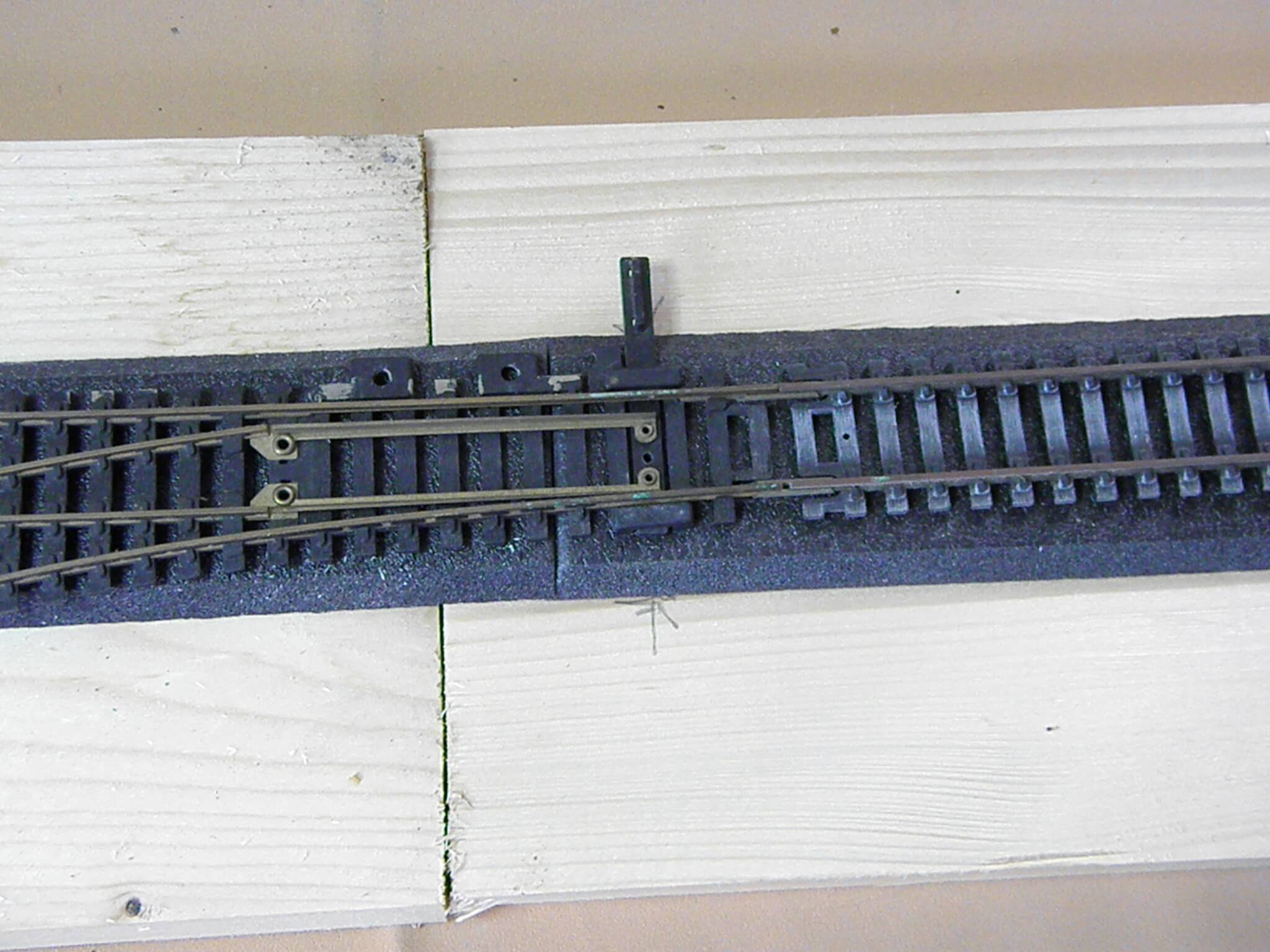
Step 1
With turnout in position on the roadbed, mark the location of the points arm. The marks should reflect the center of the arm.
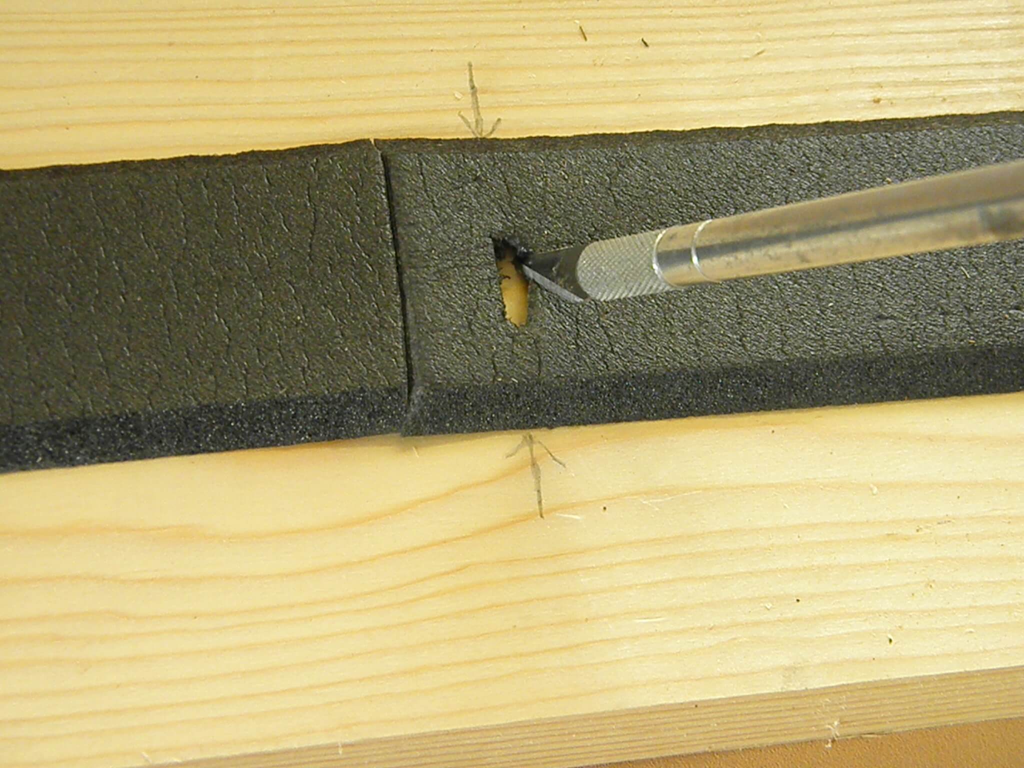
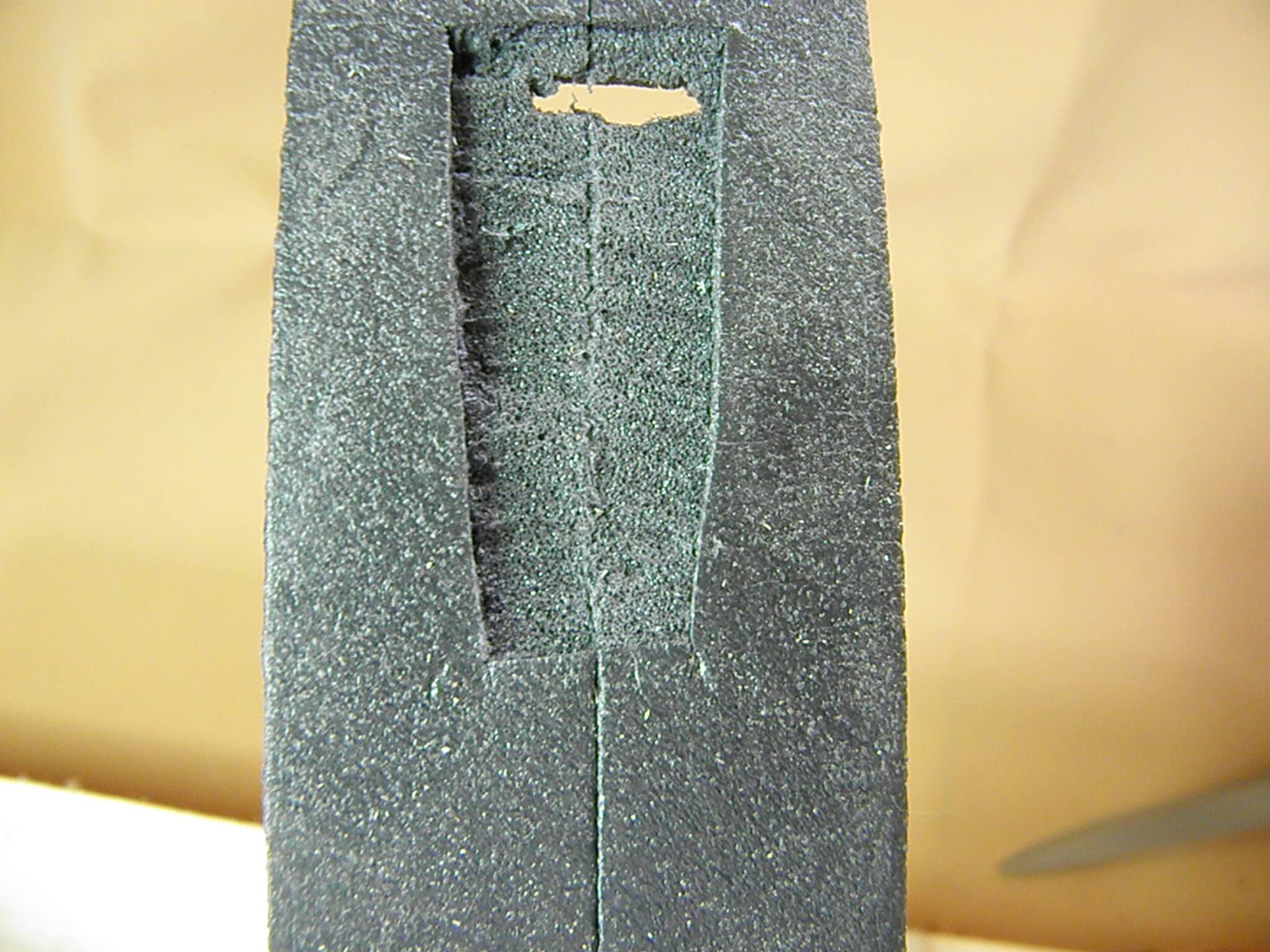
Step 2
Using a Utility Knife or a Hobby Knife, cut a slot that will be between the rails. Center it on the points arm. Cut the width less then the points arm and that will allow complete concealment.
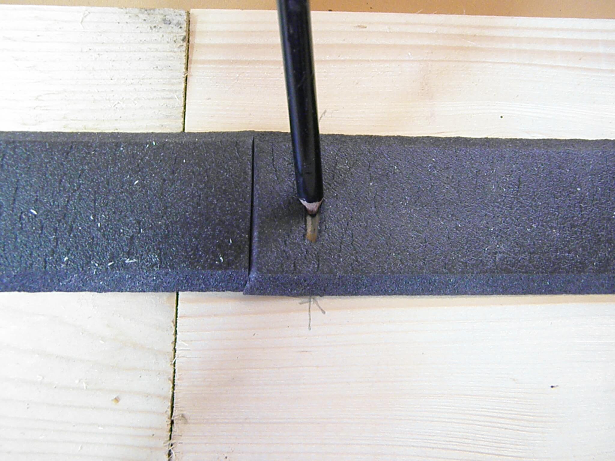
Step 3
Mark the center of the slot for reference during installation of the mount.
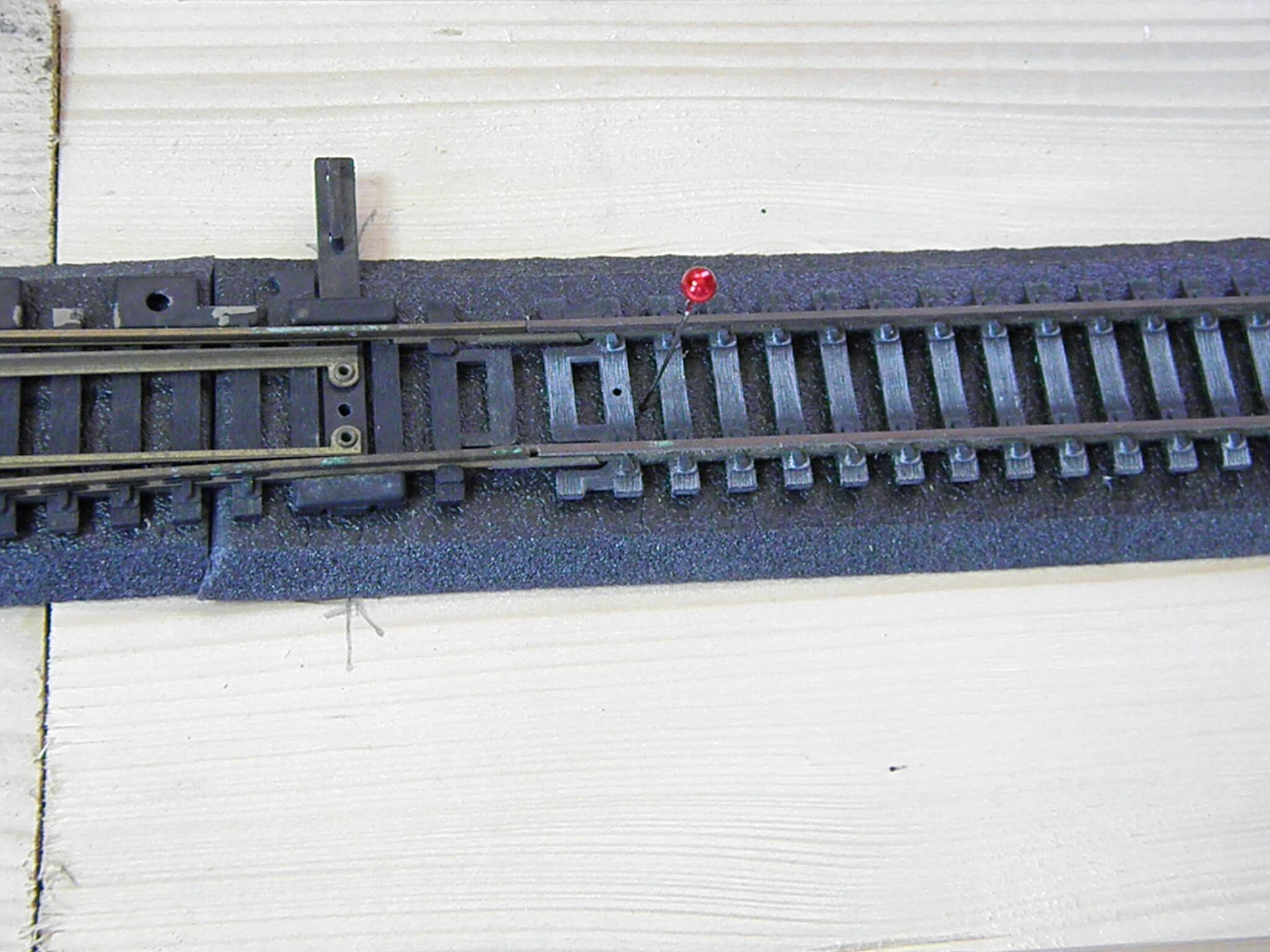
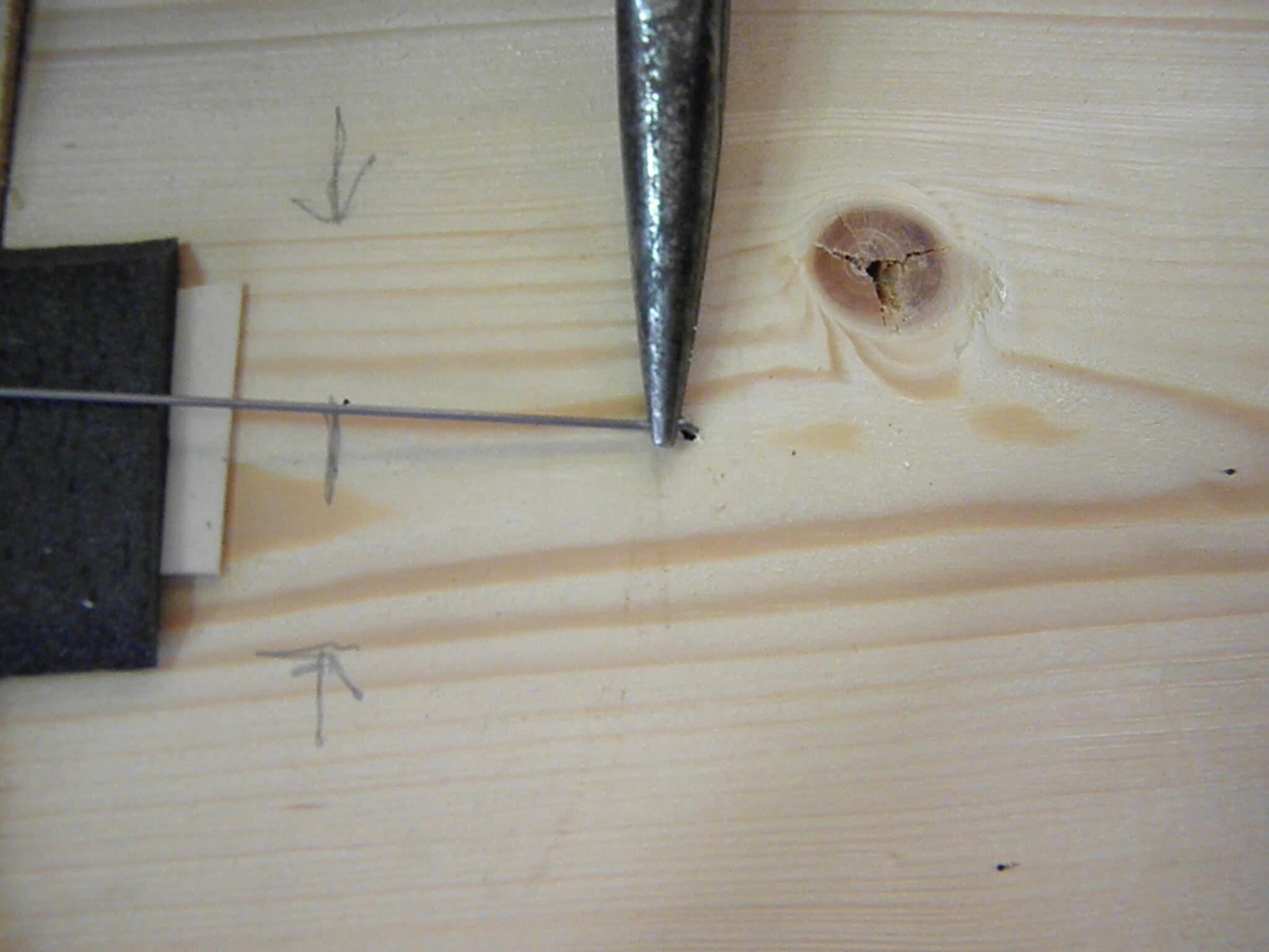
Step 4
With the turnout in position, use a straight pin or something similar to mark a hole for the linkage rod to go through. This can be done on either side of the points. Keep in mind that the software that controls the range of motion might have to have values reversed to change direction.
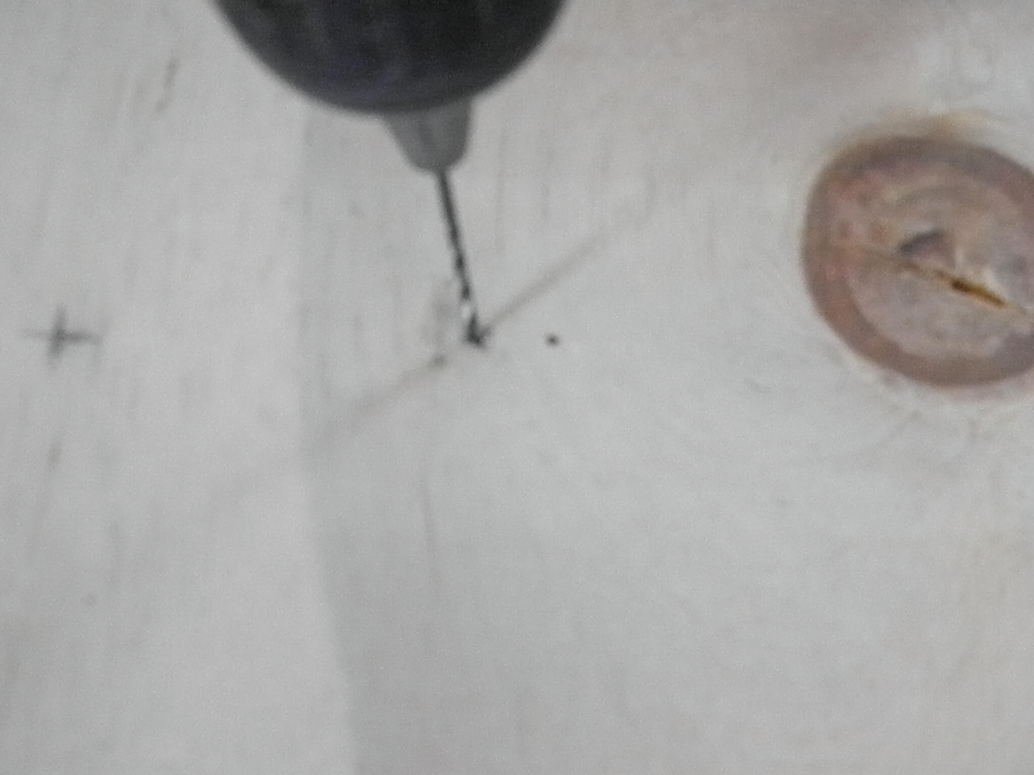
Step 5
Drill a hole in the marked spot for the linkage rod. Be sure it is larger then the rod itself. A 1/16 drill bit works fine. Keep it as straight up and down as possible.
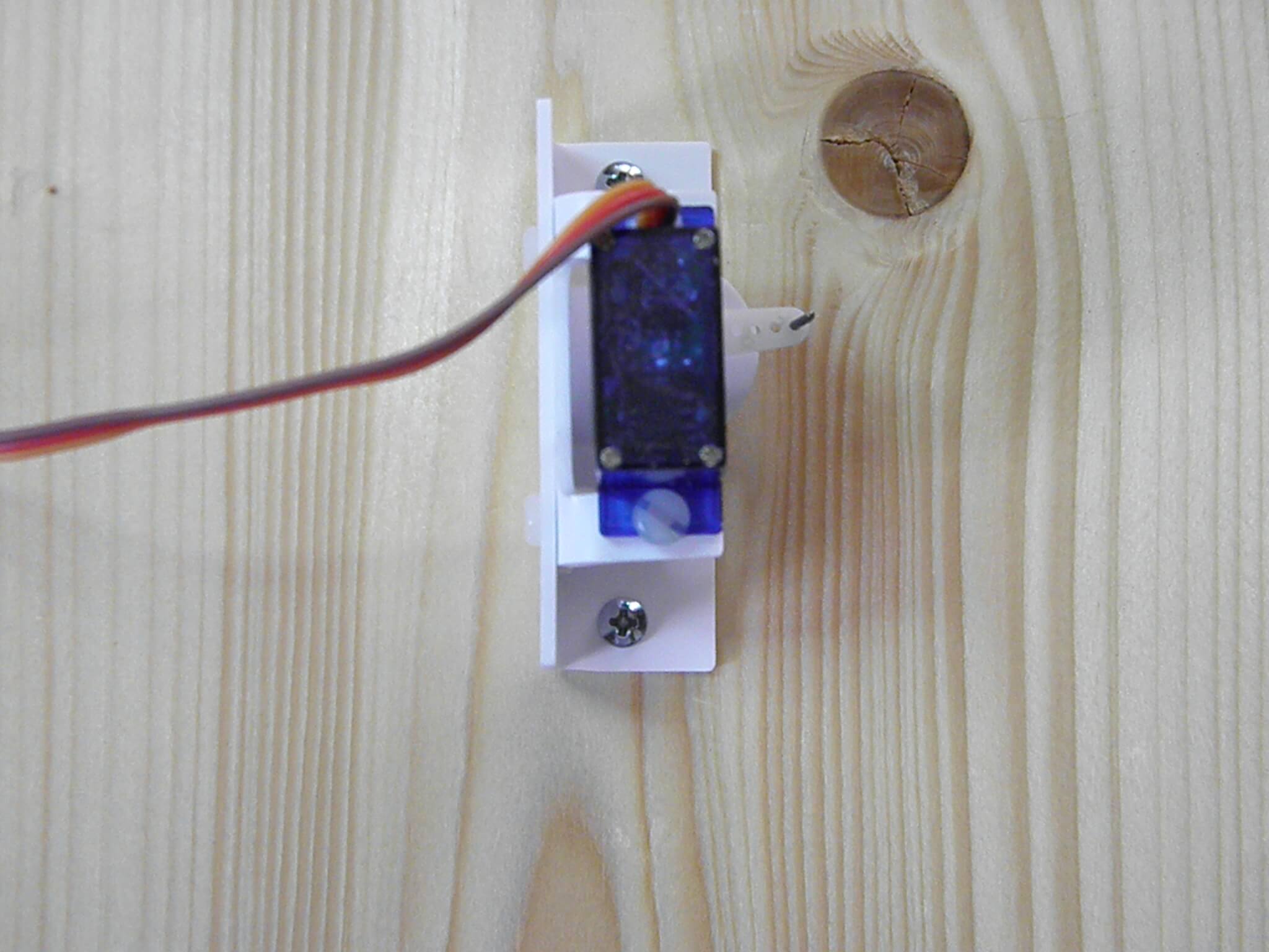
Step 6
From underneath the layout, insert the linkage rod through the drilled hole. Secure the mount with 2 screws, (not provided). The orientation of the mount is not critical as the linkage will be adjusted topside.
Step 7
Using a Utility Knife or Hobby Knife, carve a channel for the linkage rod into the bottom of the roadbed. An 1/8 inch works fine. Make sure it’s carved in the direction of the hole where the linkage arm comes through. If using a layer of foam on top of baseboard, an alternative would be to carve the channel into the foam instead of the roadbed. Either way works.
Step 8
Using Needle nose pliers, grasp the linkage rod where it come through the base. Bend it 90 degrees toward the center of the mark made earlier for the slot in the roadbed. To get it at 90 degrees you will have the bend it past 90 and let the rod spring back. You want it parallel to the base.
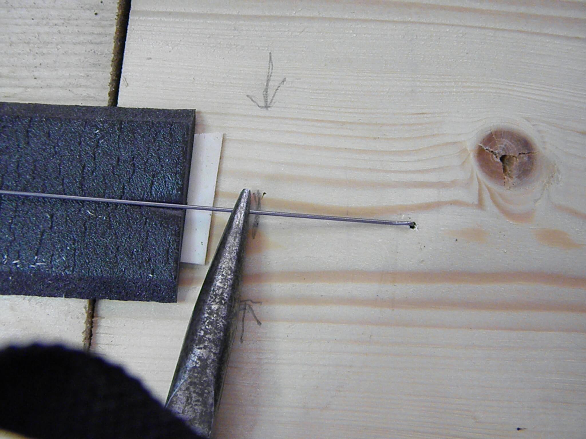
Step 9
Using the mark made earlier and the Needle nose pliers, bend the linkage rod straight up. This part is what will move the points.
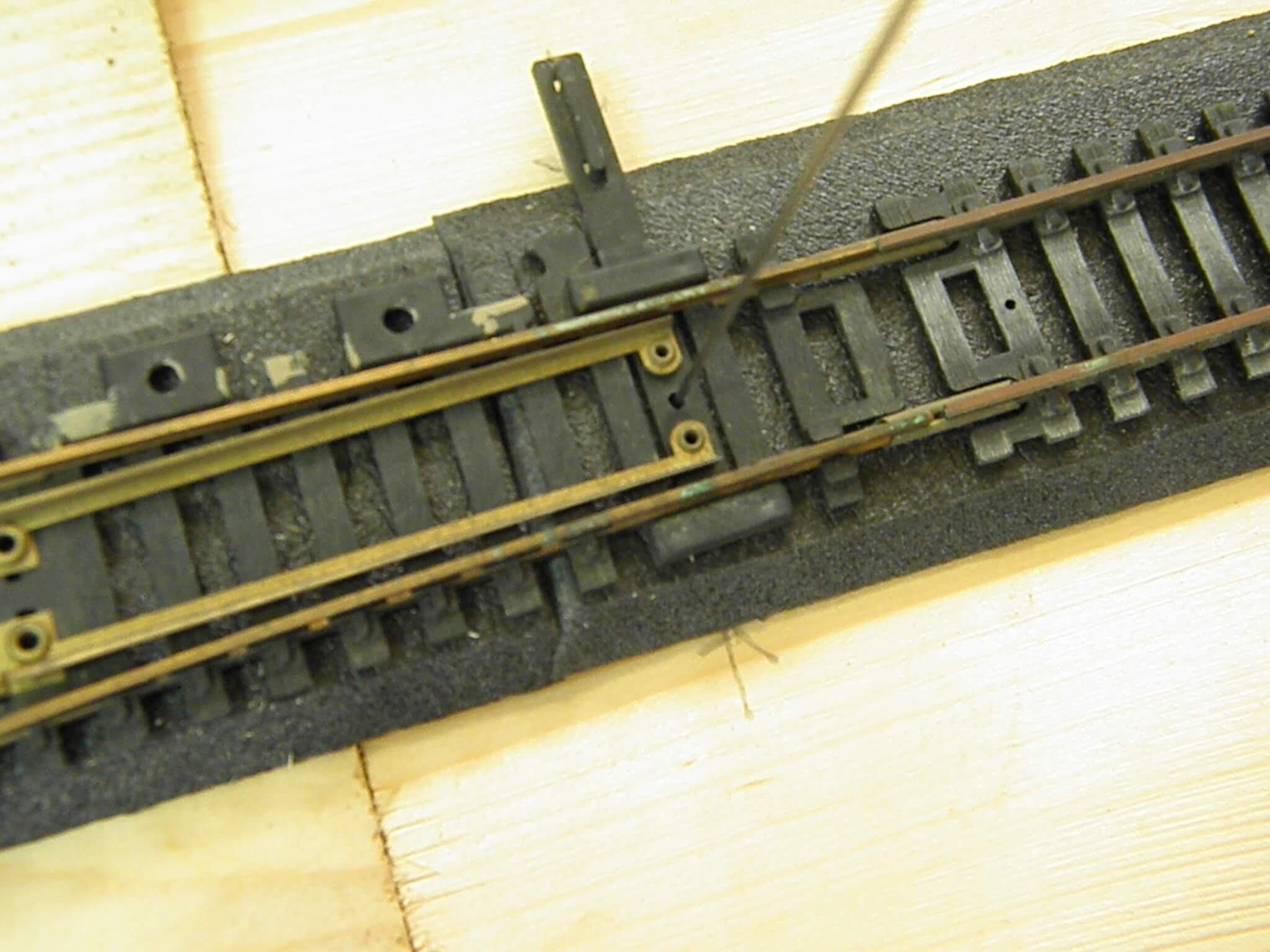
Step 10
Re install the roadbed with the linkage rod coming through the slot that was cut. With the roadbed down and secured, install the turnout by sliding the linkage through the hole in the center of the points arm. Some turnouts do not have this hole and for that, drill a hole, using a 1/16 inch drill bit, in the center between the points. Test for free movement before securing the track. At this point, tweaking the software so the points make solid contact with the rails will be needed. The spring in the metal will allow solid contact to be made. No more then a couple degrees past contact is recommended. Don’t forget to secure the track. The excess linkage rod can be cut flush with the points arm and a dab of paint matching the points arm will complete the concealment.