
User Provided N-Scale Turnout Installation
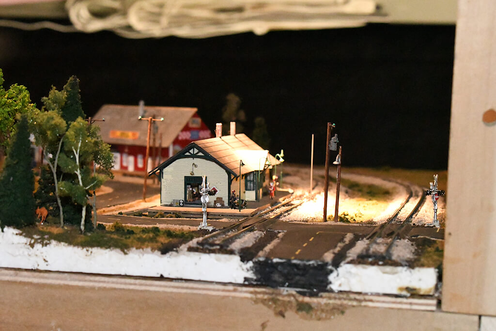
Thanks to David Tunne for sharing a picture from his layout
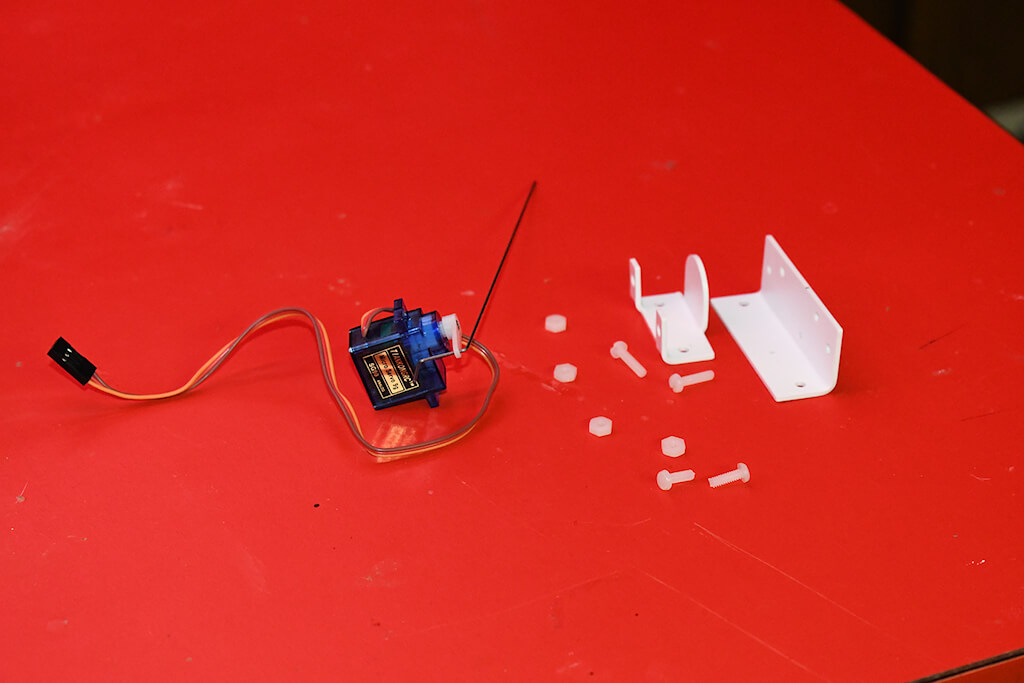
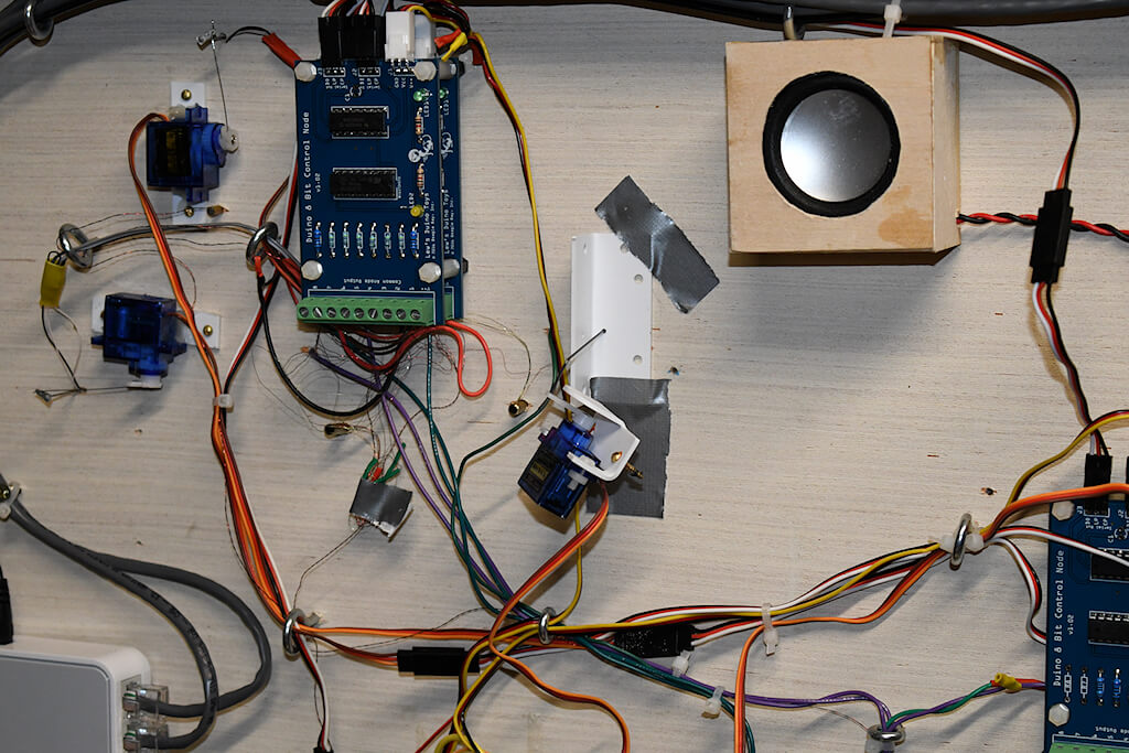
A user from Reno sent us his step by step method to install the mounts on his existing N-Scale Layout. After removing the makeshift assembly that was there he made sure that line marking the motion plane was still intact. If not, the motion plane will need to be marked. The servo mount was disassembled and the screws holding the servo in place were reversed. The linkage rod was re-positioned to exit from the back of the mount.
With the orientation marked on both sides of the linkage rod hole, the mount can be installed.
Using the linkage rod, inserted into the hole to the turnout, as a guide, slide the top of the mount up to the baseboard, properly orientate it and mark the mounting holes.
Insert the linkage rod through the bottom into the hole in the pivot point of the turnout. A second set of hands would be real handy to guide the rod.
Tape the top bracket part to the base.
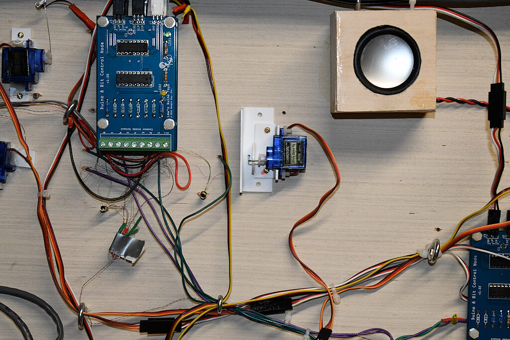
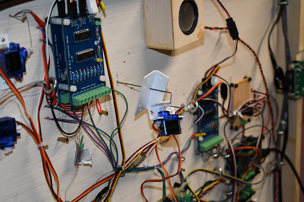
Slide the servo bracket up to the top bracket, align the holes and using small wood screws, attach the mount. Doing it this way eliminates the need to drill a recess for the servo bracket mounting screws. After mounting, test the operation and then cut the excess linkage rod off, flush with the top of the pivot point tie.